Types of Loads and Stresses in a Piping System
Pipe Stress Analysis as a Typical Mechanical Stress Analysis
The key to better understanding pipe stress analysis is to see it as a typical mechanical stress analysis. All the main topics of a typical mechanical stress analysis such as strength of material, types of loads and stresses, failure theories, allowable stresses, etc. are applicable to pipe stress analysis. In addition to these theoretical bases, many experimental and empirical results have been used for developing the pipe stress analysis methods. The experimental works on fatigue analysis of piping by A.R.C. Markl in 1940’s and 1950’s and his article in 1955 as Piping Flexibility Analysis [1] is an examples of these efforts. The combination of analytical and experimental research can be observed in the studies initiated by Pressure Vessel Research Committee in 1950’s and 1960’s that combined the theoretical analysis of Professor P. P. Bijlaard of Cornell University with experimental results. These efforts were published in WRC bulletins known as WRC 107/537 [2] [3] and WRC 297 [4] that are widely used to calculate flexibility of vessel shell and stresses due to interacting loads between piping system and pressure vessels. Each of these topics is a subject for another article and will be discussed in more details. In this article an introduction to types of loads and stresses are provided as a basis for classification of the stresses as they have been considered in ASME codes, specifically ASME B31.1 and ASME B31.3.
Load Types in a piping system
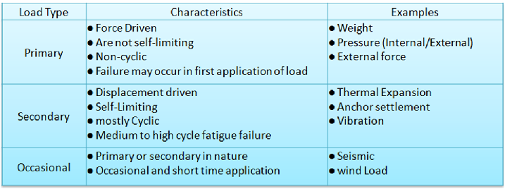
Loads in a piping system are considered in two main categories: primary loads and secondary loads. Each of these load types has their own characteristics that determine their criticality and how ASME codes set their allowable stresses. In addition to these two main categories, occasional loads are also considered in a piping stress analysis which can be in nature primary or secondary but the main difference is that their application time is short compared to primary and secondary loads. Therefore they are considered less critical and the allowable stresses are higher than primary and secondary loads limits. Table 1 shows the characteristics of these loads and some examples for each one.

Stresses in a piping system
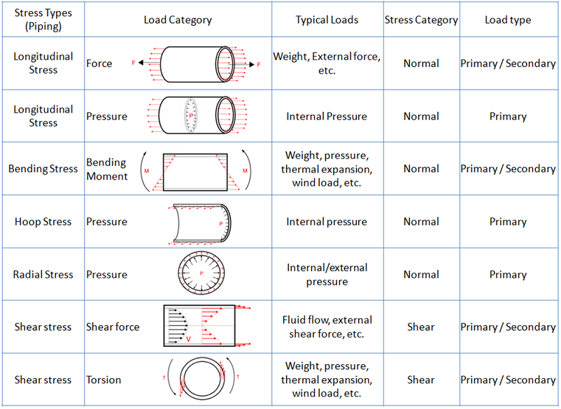
The loads shown in table 1 are source of a wide variety of mechanical stresses in a piping system. Table 2 shows the types of stresses that may be induced in a piping system and the loads associated with them.

Stress Classification per ASME Codes
The classification shown in table 2 is based on individual stress types. Another classification of stresses in a piping system is by compound stresses and the loads causing them. In Introduction to Pipe Stress Analysis this classification was introduced as shown in Figure 1. This type of classification is used by ASME codes and consequently pipe stress fotwares for calculation and setting the allowable limits.

Each stress category in figure 1 consists some of the individual stress types in Table 2, depending on the applicable code. For instance per ASME B31.3 sustained stresses consists of element from longitudinal stresses from both pressure and weight, bending stresses from in-plane and out-plane moments, and shear stresses from torsion. Allowable limit for sustained stresses per ASME B31.3 is Sh which is the allowable metal temperature at operating temperature. For more details on the equations for calculating these stresses and their allowable values, see the article Allowable Stresses, ASME B31.1 vs B31.3.
Calculation of 3D state of Stresses
A piping system experiences a combination of these stresses which results in a complex 3D state of stress. Pipe stress analysis as a practical calculation looks for a premium combination of accuracy and simplicity of the calculations. Therefore some of the stresses shown in table 2 are not considered in pipe stress calculation because of their complex equation and insignificant contribution to the total stress. Radial stresses from pressure and shear stresses from shear forces such as fluid flow are in this category.
Related Articles
Allowable Stresses, ASME B31.1 vs B31.3
Sponsor
References
[1] A.R.C. Markl, Piping-Flexibility Analysis, ASME, 1955
[2] K. R. Wichman, A. G. Hopper and J. L. Mershon, Local Stresses in Spherical and Cylindrical Shells to External Loadings, WRC Bulletin 107, 1965
[3] K. R. Wichman, A. G. Hopper and J. L. Mershon, Precision Equations and Enhanced Diagrams for Local Stresses in Spherical and Cylindrical Shells Due to External Loadings for Implementation of WRC Bulletin 107, WRC Bulletin 537, 2010
[4] J. L. Mershon, K. Mokhtarian, G. V. Ranjan, E. C. Rodabaugh, Local Stresses In Cylindrical Shells Due To External Loadings On Nozzles-Supplement to WRC Bulletin No. 107 , WRC Bulletin 297, 1984
Disclaimer: The contents of this page are for educational purposes only and are not intended to provide practical advice.
