Dynamic Analysis of Piping Systems
Introduction
Piping systems, like all other mechanical systems, can be exposed to both static and dynamic loadings. Most pipe stress analyses are performed with the assumption of static loading where the load is applied slowly and is constant after being applied to the system. However, this assumption is not true for some types of loadings. Loads such as seismic, relief device load, water hammer, slug flow, and cyclic loads from rotary equipment are a function of time. Although some of these loads can be analyzed using equivalent static methods, in general these loads require being analyzed using dynamic analysis. In this article types of dynamic analysis for piping systems and their application for different dynamic loads is discussed. The article includes the following topics:
- What Is a Dynamic Load?
- Dynamic Load Factor, DLF
- Harmonic Analysis
- Spectrum Analysis
- Time History Analysis
What Is a Dynamic Load?
A load is considered static when it is applied slowly and does not change with time. The examples are weight, spring load, thermal expansion load, and settlement. A load is considered dynamic when it is applied quickly and changes with time. The examples are seismic load, relief valve discharge load, and water hammer.
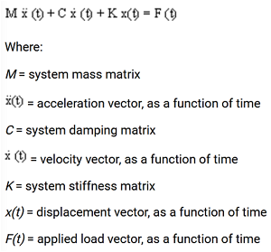
The response of a piping system as a mechanical system to static and dynamic loads is different. Also, different equations are used for analyzing each of them. When static loads are applied, the system is in equilibrium and the second Newton’s law is used to calculate the parameters such as force and displacement. However, for dynamic loading, since the parameters such as force and displacement are a function of time, the differential equation of motion is applied instead. This is the general equation that is applied to all dynamic analyses. For some dynamic loadings, the equation can be simplified by considering constant or zero values for some of the terms to be able to get an explicit solution.
Dynamic Load Factor, DLF
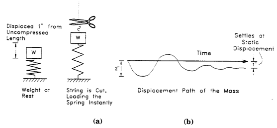
As mentioned, the response of a mechanical system to a dynamic load is different from its response to a static load. The Dynamic Load Factor or DLF is a key parameter that is used in dynamic analysis and presents this difference. DLF is a number between 1.0 and 2.0 with DLF=1 for static loading and DLF=2 for dynamic loading. Depending on how quick the load is applied, DLF gets closer to 2.0 for dynamic loads. To present this concept, consider the weight W that compresses spring with spring factor K for two situations of static loading and dynamic loading, as shown in figure 2. In dynamic loading, the displacement of spring in the first cycle can be up to two times the amount of deflection for static load. By writing the work done in both cases, DLF is obtained to be a number less than or equal to 2.0.
Types of Dynamic Analysis
Three types of dynamic analysis methods are used for a piping system, Harmonic analysis, Spectrum Analysis and Time History Analysis. Depending on type of dynamic load, the proper method should be selected.
1- Harmonic Analysis
This type of dynamic analysis is used for low frequency vibrations with harmonic functions such as vibration transferred to the piping system from rotating equipment or pulsation from a reciprocating pump or compressor. The analysis uses the differential equation of motion shown in Figure 1.
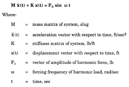
For harmonic analysis, it is assumed that the displacement (vibrations) or the force (pulsation) that impacts the piping system has a sinusoidal form with zero damping coefficients. This assumption simplifies the equation and makes it explicitly solvable.
2- Spectrum Analysis
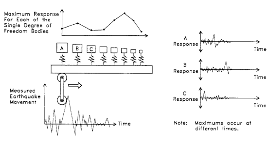
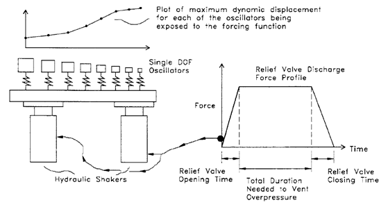
For applications with transient loads, spectrum analysis is used. Spectrum analysis estimates the responses of a piping system to the transient load for force or displacement and finds the maximum response as the basis for the stress analysis. A piping system as a mechanical system has many natural frequencies. In spectrum analysis, a limited number of lower natural frequencies that have the major contribution to the response of the system are selected and the summation of the maximum of each mode is calculated as the overall response of the system. This concept has been shown in figure 4 and 5. Spectrum analysis is used for seismic loading as a displacement driven loading and for relief valve, water hammer, and slug flow as force driven loading.
2-1- Seismic Spectrum Analysis
Since seismic loading is caused by random transient motions of earthquakes, spectrum analysis is used for it. The response of a piping system to seismic loading can be obtained by finding the response of a series of single degree of freedom oscillators to the displacement caused by an earthquake, as shown in figure 4. Each single DOF oscillator represents one natural frequency of the system. Since a complex system has an indefinite number of natural frequencies and the first ones have the major contribution, in a spectrum analysis only a set number of the first natural frequencies are taken in to account. The limitation on the number of natural frequencies is called frequency cutoff with the typical number of the first 33 frequencies.
The response can be measured in terms of displacement, velocity, and acceleration. Pipe stress analysis software uses the sum of the maximum responses as the basis for calculating the stresses that are compared to occasional stresses outlined by the relevant code, such as ASME B31.3.
2-2- Force Spectrum Analysis
Force spectrum analysis is used for impulse loading such as relief valve loading, slug flow and water hammer. These loads are not random like a seismic load and their profile can be obtained for the duration of the application. However, since they are transient loads, spectrum analysis is used for them. Figure 5 shows the profile of the load for a relief valve discharge and the spectrum of responses of the system. The system’s natural frequencies are shown as single DOF oscillators.
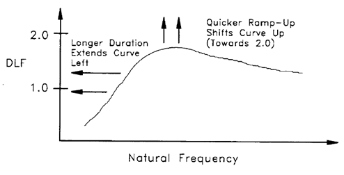
In the seismic spectrum method, the spectrum of displacement, velocity, and acceleration was used. In the force spectrum method, a Dynamic Load Factor (DLF) is used instead. As we know, the impact of a dynamic load on a mechanical system can be up to 2.0 times that of an equivalent static load. Figure 6 shows a graph of DLF for natural frequencies of the system. As expected, if the ramp-up is steeper, the maximum DLF is closer to 2.0 because the load has more dynamic characteristics. Also, as the duration of the loading increases, the graph shifts to the left and the lower natural frequencies will be more excited. These impacts are shown in Figure 6.
2-3- Dynamic Analysis vs. Equivalent Static Method
Relief valve discharge load for open systems can be analyzed using equivalent static analysis instead of dynamic analysis. In this method, the reaction force during discharge is used that is provided by the manufacturer or is calculated with the equations provided in API 520. The reaction force is applied as the equivalent static load to the elbow upstream of the exhaust. To be more conservative, the calculated load can be multiplied by 2 to take into account the dynamic load factor. The equivalent static load is considered as an occasional loading. Similarly, seismic load can be analyzed using an equivalent static analysis that takes acceleration g multipliers as input. Static equivalent analysis is simpler but dynamic analysis is more accurate.
3- Time History Analysis
Time history dynamic analysis is the most accurate and the most complex dynamic analysis. This method can be used for most dynamic loadings, but due to the complexity, it is used mostly for loadings that can not be solved with other methods, such as relief valve discharge in a closed system. In this method, the duration of the dynamic loading is divided into smaller time slices. The equations are solved for each time slice to provide an overall evaluation of the response of the system to the dynamic loading. In each time slice, the parameters such as displacement, velocity, acceleration, and force are solved at each node and for each mode of vibration. This analysis is applicable when the profile of the load is known, such as relief valve discharge load, slug flow and water hammer. Therefore, it can not be used for seismic loading.
Related Articles
Types of Loads and Stresses in a Piping System
Allowable Stresses, ASME B31.1 vs B31.3
Sponsor
References
[1] Intergraph Pipe Stress Analysis Seminar Notes, COADE Inc.
[2] CAESAR II Users Guide, Hexagon PPM
Disclaimer: The contents of this page are for educational purposes only and are not intended to provide any form of practical advice.
